Monday, December 15, 2014

Modeling Latrobe, Flonellis, east and west

One of the reasons I chose to model the Placerville Branch was due to its close proximity to home. I've spent some time driving by and over the branch, walking its trackage and recently riding the Sacramento and Placerville Rr from the very east end of Folsom up to Latrobe.
Site of the Latrobe Station 
Latrobe Station
CSRM used with permission

The new Latrobe station in or around 1914. The track directly in front of the station curves to the right toward the main and was most likely the freight siding for cars loading and unloading at the long freight pier connected to the station. Typically these were stub ended, but I cannot tell from the photo. The freight pier has a wooden dolly parked near its far end as well as, what appear to be stacks of filled burlap bags. The track to the far right curves to the left and is probably the Latrobe siding. A velocipede sits between the main (center) and the siding on the right. The station appears brand new and is painted 2 shades of what I assume is colonial yellow as was a standard in 1907. I can only imagine 7 years later that it was still standard.This is close to a  SP  station CS Common Standard #11. If you know otherwise, please let me know, but I am mostly suspicious about the wall paint colors I've described. Could they have been brown? Lastly there is no date on the back of this photo, so its not clear when it was taken, however I understand that the original station burned ( the one captured below top  right) in 1914 and that the station above was built to replace it until it was shut down in 1924.

Upper & lower right Latrobe Station pre 1914
Upper & Lower left Simas hotel 
I wanted to understand what Latrobe might have looked like in the early part of the last century. I wanted to capture in miniature - not in a precise or prototypical way, but in a way that sets a stage for what a very small foothill town might have looked like in those days. There were  2 scheduled passenger trains that stopped at Latrobe until the late 1930's. McKeen Car 45, headed EB at 4.30am, then again WB at 7.36am. I have no data as to passenger service before the McKeen car era. I do have some poorly scanned photos which show horse drawn wagons as well as early automobiles lined up at the station waiting for passengers. So more scheduled passenger trains previous to 1931 may have been the norm. I've taken a look at several of the train sheets in the 1930's and the crew names were always the same. I suppose the engineer and conductor were not about to allow anyone else to fill these positions. Times were hard in America during that time period and good jobs were not so easy to come by. Lastly note the upper right photograph that a train order board is sticking out over the roof. Next time I'll write of other influences I took from these and other Latrobe scenes and how I used various freight services provided by the railroad and some imagining to come up with my modeling scenes of Latrobe. Next time!

east Latrobe scene on the Placerville Branch


Friday, December 5, 2014

Electronics

The electronic/electrical work on the Placerville Branch was installed as the bench and trackwork went into place. I've owned early digitraxx and now NCE systems. I prefer NCE, Since the Placerville Branch is 1. dark territory and 2. a smaller railroad, I think I'm set with NCE and its advanced consisting capabilities, along with decoder programming help from Decoder Pro 3. Area electrical blocks as part of short management were created by gapping and isolating trackage into 5 blocks. When operating, I don't care for electrical shorts shutting down large sections of Rr, so I broke the Placerville branch into 5 separate electronic zones each fed with a TTX circuit breaker.  #12 ga wire was utilized for the primary buss. I used solid 26 gauge wire tips soldered to code 73 visible track and the Atlas code 83 track in staging.  The 26 ga. was in turn soldered to 16 ga stranded which in turned were fastened to the buss with suitcase connectors. Its been up for couple of years now and some issues during  ops session have come up. A loose wire to a ckt. bkr. shut down upper Placerville at the end of one session. Improperly chained circuit breakers, which in turn weren't isolated at track level, caused delayed control issues and random shut downs that would last for several seconds. As much as I didn't want these trouble occurring on the Pville branch, they have. I think I've worked through most of them now. Contrary to what many modelers think is proper, I power my frogs for polarity so that my small engines  - which is what we have here on the Placerville Branch, glide across turnouts. I utilized 2 types of switch machines; Tortoise machines throughout Folsom yard and Blue Point manual machines everywhere else.
That is until recently. I've started replacing blue points with Tortoise. Reason? I don't think you can beat the stall power of a switch motor - the points are driven into the stock rail and stay there. Additionally the Tortoise is a bit more forgiving in terms of mechanical alignment. I've learned that unless the blue point is in perfect alignment I can't get proper point closure. Switch wiring is pretty basic for either machine. Tortoises have one motor side going to12vdc ground, while the other motor side is wired through a spdt switch, one side of the switch is wired for pos. 12vdc, the other for neg 12vdc. You flip the switch the Tortoise drives one way or the other. I wire the frog by utilizing a pair of switches on either machine to flop correct power back and forth between stock rails and the frog. This is one way to prevent locomotives from entering the switch against the points and derailing. It creates a short and stops the loco. Of course if you back into the switch with a long string of cars leading the way, all bets are off.
Lastly I was encouraged  to bridge the gap at the points with fine #30 gauge wire. I did this for the first 40 switches or so, but ran into trouble when using blue point manual switch machines. The fine wire or my questionable soldering would pressure the point in one direction opposite to the desired switch throw direction and I wouldn't get full point closure. Eventually many switches wired with the fine #30 wire were taken out. Not the switch, just the wire. I may have point electrical contact issues going forward, but so far so good.
Layout lighting is a combination of overhead parallel 3' T8 daylight 32 watt fluorescents. These run the entire length of the layout directly over the upper deck and it provides good light for operators. I know this because no one complains.
On the lower deck I use CFL 65 and 75 watt daylight bulbs. Recently, I'd thought I'd try some Home Depot LED bulbs, however I didn't like the color of these and the CREE LED daylight, which I prefer are prohibitively expensive.  A railroading buddy, gave me strings of led surface mounted white lights which softly and yet effectively light up staging under the penninsula.
Lastly my staging area is driven by the NCE throttle macros which drive the switch machines into proper alignment depending on the track chosen and whether its an inbound or outbound train.
Thats it. I'll start writing about the modeling, the structures, the towns and building out the Placerville branch next time out.
My wiring is very basic, because it doesn't need to be anything else. No detection, no signalling, excepted for a couple of planned TO boards going up at 2 locations. You can't control my turnouts with DCC except in staging so all my wiring consists of the buss, the track feeders, 12vdc turnout and frog control.


Saturday, May 31, 2014

trackwork 2

I was looking through my collection of books and magazine articles I've collected over the years on laying track and I'd have to say that no matter how much I read, it doesn't help me near as much as actually doing it. The idea is that reading gives you knowledge, but experience is the teacher. This holds very true for me. I know how my code 70 ME track is supposed to look; straight, level, without deviation vertically or horizontally. My turnouts correctly aligned, the throwbar centered directly over the control wire hole and when the tortoise or blue point is connected an equal point swing in both directions as the point rail pushes up against the stock rail. My NMRA track gauge confirms what I see or think I see as the case maybe. Something working sometimes is just not as good as something working all the time. The occasional pick of a point by a 40' box rolling over a switch happens for 5  main reasons that I've experienced.

1. there's a problem with the box car
a. wheels - dirty, distance between wheels is wrong,
b. car - weight too light or shifted to one side causing the car to lean.
c. trucks - mounting screw too loose or tight against the mounting post or both trucks mounted too tight or too loose. One truck should be mounted slightly looser then the other providing a counter balance along the car as it rolls over the track.
d. everything else

2. there's problem with the turnout
a. controlling direction point rail not snug against the stock rail, or gap not correct on the open point rail, points not level and sitting above the stock rail.
b. dirt or debris in the frog or flanges, soldered frog wire is too high and interferes with car wheels as it rolls over these connection points
c. everything else

3. theres a problem with the switch control 
a. under the layout machine; blue point, tortoise, not mounted or aligned to turnout correctly.
b. control wire not centered equally on either side of the control wire hole, too light a gauge control wire.
c. everything else

4. couplers
a. coupler height maybe, but mostly the couple swing is restricted or not freely swinging
b. everything else.

5. operator error
a. panic throw of switch points under cars
b. partial or wimp throw of blue point
c. everything else.

Surely there are other reasons for the occasional derailment at the switch which is where they occur on the Placerville branch.  Outside the turnout itself, for example at incoming and outgoing switch connecting tracks not properly aligned. They should be no abrupt angles between adjoining track pieces. In fact no differing angles at all. Put a small hand mirror on top of the rails and look down the track through the mirror. It will  reveal any and all kinks that have developed.
All in all it isn't easy for me and other modelers to get this right. All of us have our own strengths that we bring to the table. Take your time and don't quit until you do get it right. This may take days or months, but keep plugging away at it. Zero derailments is the goal after all.


Sunday, April 27, 2014

Trackwork

After several attempts at building a model railroad I've come to one forgone conclusion:  I needed to put the quality of  trackwork above all else and so have a consistent high standard as my skill level would allow. Standards help define the quality of the work and if you hold yourself to it you'll succeed.
Here a list of track laying activities and notes.
Minimum mainline radius is 24" with moderate easements.  Room width and layout design limited track radius. Small steam and first or second gen. diesels look OK on medium curves. Mostly 4 axle diesels powered the branch in the 60's and later. That would be GP9's and 38's, as well as an occasional SD9E.  In the steam era 2-6-0's moguls, and 2-8-0's consolidations ran on the branch, with occasional Pacifics allowed but not often seen. Micro Engineering code 70 is used throughout the modeled portion; Atlas code 83 in staging. The turnouts in the modeled portion are ME #6's with  Atlas#5's in staging.
Track is on cork roadbed.  Cork, which I've used time and again, does not seem as good a sound deadener as homasote.  Other then that I have no complaints. Yard and/or broad areas with multiple tracks are covered in midwest sheet cork, everything else is on HO scale midwest cork strips with the standard beveled edge.
The track plan was roughly transferred to the plywood via the "look at the computer, read the various measurements, ie length, radius, distance to various points etc" method.  A more accurate transfer is to print out 1:1 centerline drawings of the track work, laying it down on the subroadbed and using a  pounce wheel or other methods to transfer the centerline. The constraints here are having access to a large roll printer or piecing together standard 8.5" x 11" sheets to create a mosaic. I've used  both methods. I ended up transferring measurements from a model railroad CAD software program, in my case 3rd Planit, directly to the layout. Below shows the beginnings of Folsom yard, with some trackwork already in place. If you look closely you can see a portion of the drawn lines on the cork extending from the switch in the center of the photo

There are hundreds of magazine articles and several books covering track laying techniques. These are the methods I used in constructing track work for the Placerville Branch. Again I have to thank Phil Gulley for his help in getting this work sorted out. 
Switches or turnouts are laid out first, followed by the connections via flex track in between. Prepare the turnouts by cutting out at least 1 tie at each of the three ends. This makes room for sliding the rail joiners onto rail ends in most cases. After tie removal, use a single cut mill file at each rail top and bottom to remove any manufacturing burrs. Take it easy - the ME track is not robust. I typically counted 5 to 10 file strokes for each rail at each position. Smooth the top, the bottoms and the square the face of each rail. Lastly create a point on the foot or bottom of the rail.  This helps slide a code 70 rail joiner into position. In the above photo you can see the gaps created by the tie removal . They get filled in later. We removed the manufacturers points spring allowing the tortoise or blue point to do its job without spring resistance. We checked every switch with a NMRA track gauge to ensure that the point and flangeway spacing was correct. Many of the ME flangeways were tight and had to be filed. Also at times frog rails would be higher then the rails around it, stock, connecting, etc., so I would flat file this area as well.  Lastly I wired 30 gauge wire across the point to closure rail connection to ensure electrical continuity at the points. Later I regretted doing this, as I found my solder and wire position held across the two rails would cause undue pressure on the point rails, enough so that some switches would not close properly in the normal or diverging positions. The only remedy I found was to remove the 30 gauge wire across the gap. I never figured out how to perform this task so that this would not happen, but I assume it had to do with the amount of solder used. Go light is my only advice.
I drilled ¼" holes for the .039" control switch machine wire, then set the switch in position, ensuring its correct alignment. When setting the switch into position its important to mark the 3 positions, diverging, normal and at the points. Lastly mark the center of travel for the point rails at the throwbar to mark the 1/4" control wire hole.
My trackwork is secured using clear loctite construction adhesive. After marking remove the switch one more time. Lay down the clear adhesive and spread it with scrap so the switch will cover it. Don't use too much, as ideally your track piece simply covers the adhesive and doesn't seep up between the ties. Careful around the control wire hole and  switch points. They must remain clean of any adhesive. We used push pins the hold each piece in place and let to dry overnight. The next day we removed the pins and had our turnouts in place.
I think the argument could be made that gluing down track work is risky as opposed to simply nailing it down or using white glue, where water can be used to break down the glue later and save the piece(s) for reuse. I know its an argument because I've operated layouts where this was the case. I'm just not of that ilk. I didn't want a temporary solution, but a permanent one with no movement, and I'm not going to reuse any of the track. If your confident of your plan, it's easy to put it in place.
I can't recommend enough having a copy of John Armstrong's Track Planning for Realistic Operations.
I leave you with a photo of track work in process at the Flonellis grade on the right and the beginnings of Dugan Springs on the left. In this photo the peninsula has been built and the lower level backdrop is in place.
Lastly this points to a pdf that I like alot; Turnout PDF


Wednesday, March 19, 2014

Benchwork - onward and upward

The Placerville Branch ran from Brighton to Placerville with a ruling grade of approximately 2%. So it is with the modeled version of the prototype. With the room empty I used an inexpensive laser line tool from Sears. The tool is typically used for hanging photos, art work etc. evenly on a wall. I mounted it to an camera tripod and placed it in the approximate center of the room. I measured from the floor at the tripod, to the red laser line emanating from the tool. I used 40" inches as a baseline, which is the height of track work at Folsom. I marked this 40" line around the entire room and then built my benchwork relative to these marks. There is a 2" or 3" slope to the floor which is why I chose the center of the room as a reference point. Now my benchwork is nominally referenced from one point and not to a sloping floor line.
I'll talk about staging later, as well as each and every modeled element as I get further into this, but now a few words about general construction. As can be seen by this photo below I used 3/4" 8 ply furniture grade plywood for all basic benchwork construction. I got this idea from Phil Gulley who built the Sumpter Country Lines using similar construction techniques. It has also been suggested in the model press over the years. Furniture or higher grade ply is very stable building platform for my California environment.

Displaying IMG_0280.jpeg

 The photo of benchwork construction at Flonellis shows most of the cantilever type  benchwork building techniques employed including angle brackets sitting on wall mounted plates, as well as straight joists tied to a 2 piece bracket. The 2 pieces are made up of a triangle bracket, a gusset as it were, tacked to a side of rectangular mounting plate screw mounted through the wall stud. Then my support pieces run against the plate and along the gusset plate for a very strong support. This is another Phil Gulley design. I borrowed his template for making this 2 piece bracket and made them for the entire layout in less then a days work. If your going to use your wall studs as the backing for those mounting plates please remember to mark the center line of every wall stud somewhere on the wall where it can be seen and appreciated. You'll still need to drill a small exploratory hole in the wall to ensure that your line is accurate, but once that is understood you'll have a strong interface between the stud and your plates. Note that only wall mounted plates and risers for adjusting sub-roadbed height utilize screws. Everything else is glued, then nailed using an 18ga nail gun with appropriate size nails for the job. If I thought there might be adjustment needed to a particular benchwork element I used screws, mostly though its 18ga brads and glue. Lastly remember to drill or predrill your holes for wiring. My wiring was going to be pretty simple. Control wiring, tortoise switch power in Folsom and 115vac lamp wiring for lower level lighting. So 3 holes in each joist was all that was ever required.
Trackage has started to appear; this specifically being the staging lead going up grade to Folsom. We had to do this because that staging lead is under the first deck. There is no second deck as of yet.

Displaying IMG_0275.jpeg
the photo on wall is inspiration I guess - photos of Latrobe
and things to come

Another view a little bit further upgrade from the first photo. My trusty 2' level is on the bench top. A 1/2" dowel slipped under one end of the 2 foot level approximates a 2% grade when the bubble is between the marks. On a calculator take the % of .5 to 24" = 2.08%. I tried to stay on the low end of this, meaning under 2% through out, but I always kept at grade except where spurs, sidings or towns dictated otherwise.  I used mostly cookie cutter cutting techniques so that my road bed follows grade, but the surrounding area does not. Its not always this way in the real world so somewhere on the layout the entire benchwork is at grade..more about that later. There is only one leg to support the layout so far. The benchwork is over 30" deep at one spot in Folsom, but generally less then 24" and sometimes as narrow as 10." Found the photo's below this morning. I think they better represent the initial stages of benchwork support around the wall.
More later.
early stages showing bracket supports

boxes being built off the L girder

Folsom - one day!


Monday, March 10, 2014

Benchwork - some thoughts on my design process and modeling philosophy

S curve, Latrobe, Ca. Placerville Branch

Several modeling friends and acquaintances  helped with the layout design and planning process. Phil Gulley, patiently guided me through many of the pitfalls of yard design, as well as siding and spur help. Dave Bayless helped me early on with the general shape of the Placerville Branch within its long narrow rectangular boundaries, Dave Clemons suggested NOT USING A HELIX in my double deck design.  Other artistic and engineering talents have inspired me. From the artistry of Harry Brunk, George Selios to those that create entire railroads worlds like Tony Koester, Allen McClelland, and more recently Mike Confalone, as well as the small railroad designs of Iain Rice. Of course none of this would have been possible without my well worn copy of Track Planning for Realistic Operations by the late John Armstrong. I figure this is my last chance at this. I have no intention of  starting anew and doing it again as my age affects everything from balance, to eyesight, to manual dexterity. I still have many models to build, many scenes to create and though I never plan to "finish" this thing I would like a fully scenic, miniature version of the Placerville Branch that ran from Brighton to Placerville, Ca. Operations and the socializing it brings with like minded individuals is important to me as is the physical plant.
The following links, lower level Placerville Branch and upper level Placerville Branch will take you to my google drive. Scroll down the list to view the lower and upper level layout plans. The design, done in 2010 has changed over time, but the shape of it and its semi prototypical feel has not. Without a long, detailed and sorry, boring list of all my reasons for its design, I can summarize in a few sentences. I used what history gave me,  not on one day, but over a large period of time. I combined what I thought would make an operationally interesting model railroad, based a on specific prototype. So was there ever a yard in Folsom?, sure in the late 1800's when the CPR carried passengers from Sacramento eastward and home again. Was there a Latrobe Dairy Coop?, no, but if you visit Latrobe today there are still endless acres (yes they are disappearing) of livestock range land. A dairy COOP seemed prudent. Or the Amador Copper mine, which really existed, but was never rail served. Wagon loads of copper ore were brought by wagon train up to an open platform in Latrobe where westbound freights took them down to Sacramento for smelting. Dugan Springs lasted all the way out to the end of service in the mid 80's and Camino visa vie the Mich/Cal  lumber co. provided millions of board feet of prime sugar pine lumber to help build American homes. I like history and it was important to me to base this thing on some reality. This is a western Sierra Foothills railroad and my hope is that when you enter the room, under the porch, you'll get that straight away.

upgrade and westward toward Folsom. White Rocks, Ca
Latrobe curve


A quick note about the photo's. Taken in the hot, dry California summer months. If I took these same photos today (March) everything would be green.

Thursday, March 6, 2014

Room Construction 3 - electrical notes and finishing off

In my last post I said I would write a bit about the electrical service to power up the railroad. Like everything else except for maybe scenery I run it as close to the bone as possible. Basically there are 5 outlets in the room served by 2 15 amp circuits. 1 circuit powers lighting, tools, vacuums etc. I used a 4 position lighting switch mounted right inside the doorway to access overhead room and partial layout lighting (the overhead fluorescents), a outside light above the door and then dedicated switches for nearby outlet power. First and foremost I have to say I'm happy with the amount of power available. The layout, the room doesn't require anymore then  30 amps to run. Have I blown a breaker on occasion? Yes....but only on occasion when power tools, vacuums, and a portable air conditioner were all in play. I really wasn't inconvenienced by it and never felt the need to power up the room with even 20 amp breakers. It works for an HO scale layout of this size. The other thing I  did was to ensure that the power to run my NCE control system was separate from the rest of the room. The circuit for this was run through 3/8" plastic conduit sitting external to the room walls so I can get to it if needed. The rest - lighting, outlet wiring are all inside the wall where they belong.

drywall
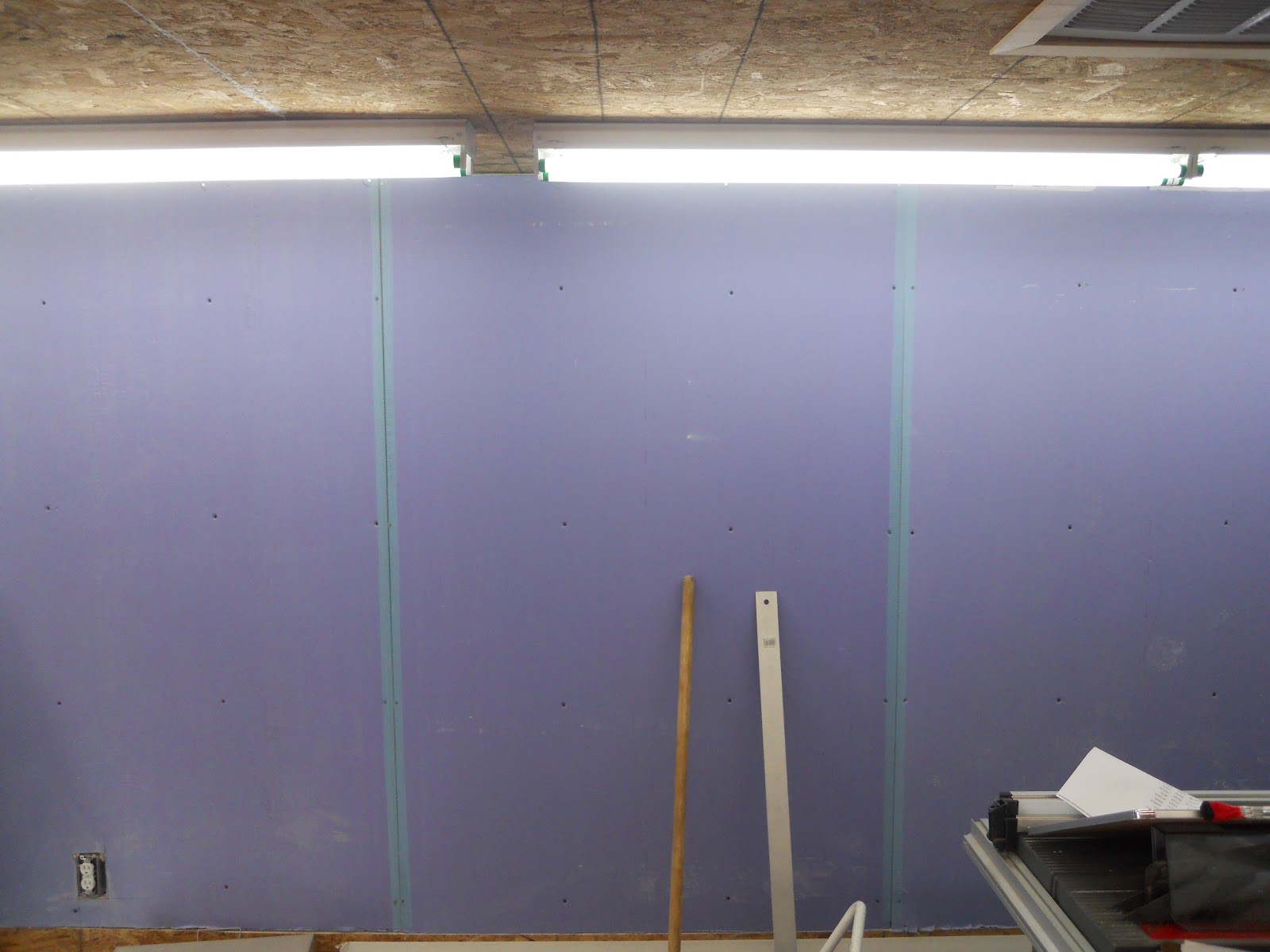
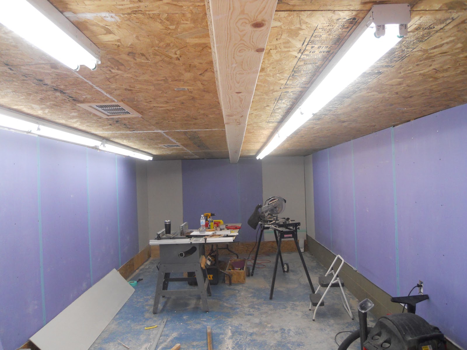
Next came the drywall. I enlisted help from my friend Phil Gulley to help with this. He assisted with all the mudding, sanding and so forth. An area which I have little or no expertise. All drywall is 1/2 inch and as can be seen from the photo I used water resistant material "just in case." Note also that the drywall does not run to the floor, so if rain or drainage problems cause water pooling on the floor it won't wick up thru to drywall, but simply wet the ledger or kick board at the base.

room before radiused/coved corners were installed


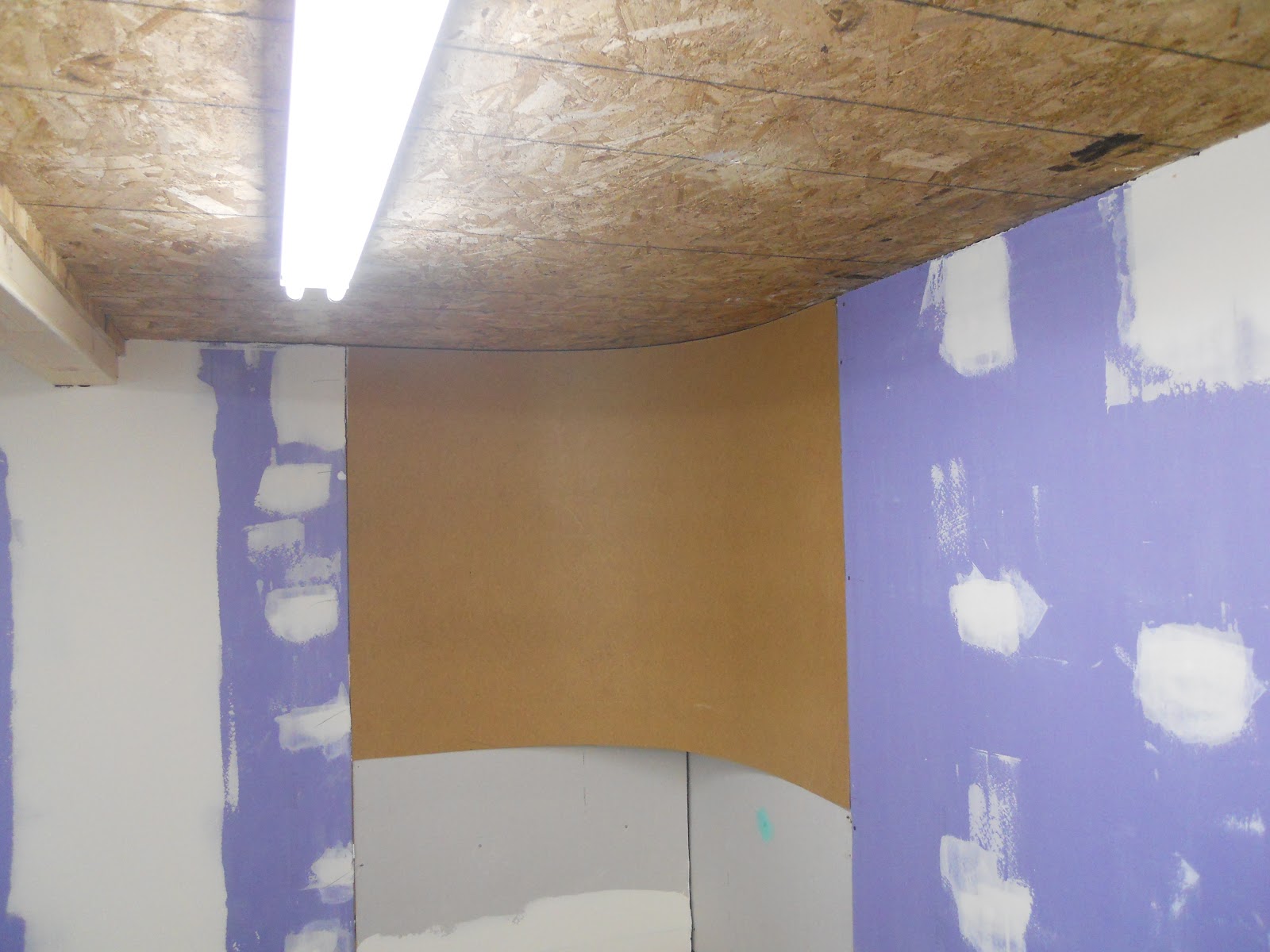
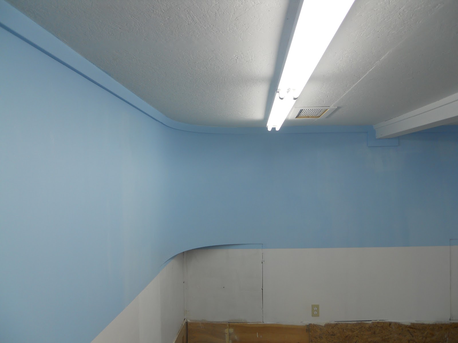
coved or  radius corners
Easier then you might think. I put 1/4' fill strips at either end where the coved masonite corners meets the 1/2" wall. Then I popped the curved 1/4" masonic in place, securing it with drywall screws on either end. Taping, mudding, and sanding followed. Note the straight room walls were already being worked as mud has been applied to cover seam tape and screw holes.


drywall in process and nearing completion

Note my attempt to add natural venting into the enclosed room. My home foundation is adjacent to the wall on the right. Before adding the ceiling a built wooden vent channels running from under the home to the room. It provide a bit of cool air in the summer time and didn't cost me anything to facilitate. There are three of these in place.

Just about ready for layout construction
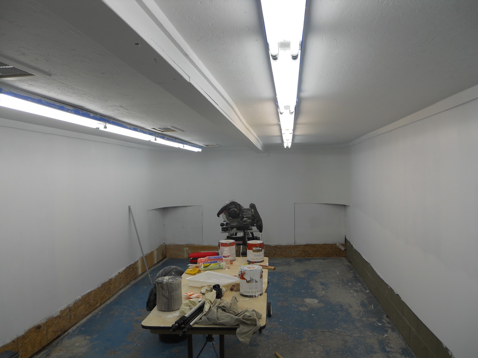
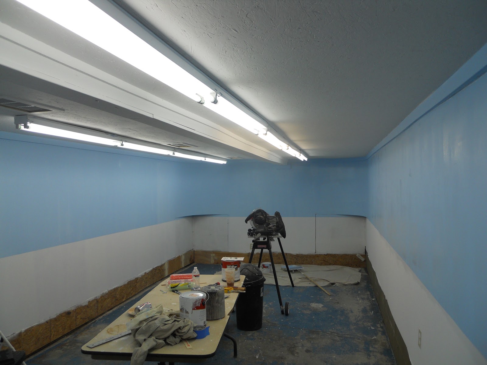
The room been painted white and almost has a sterile clean room look to it. Hmmmmm - wonder who spent their career in high tech clean rooms? The ceiling by the way, since I haven't mentioned it yet is 3/4" composition or roof grade ply. Lastly I painted my sky blue Home Depot Monaco 550-3C blue. Phil Gulley chose it on his Sumpter County lines. I find it a perfect natural color sky blue.


So now the room is ready. Its time to get the benchwork started. See you next time.

Yet more room construction photo's

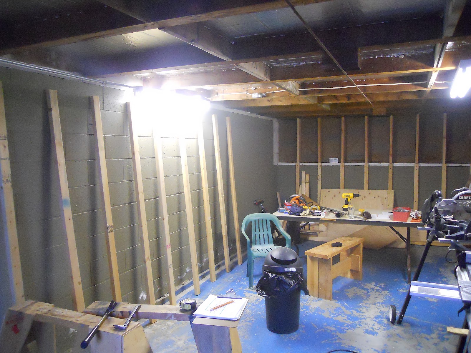
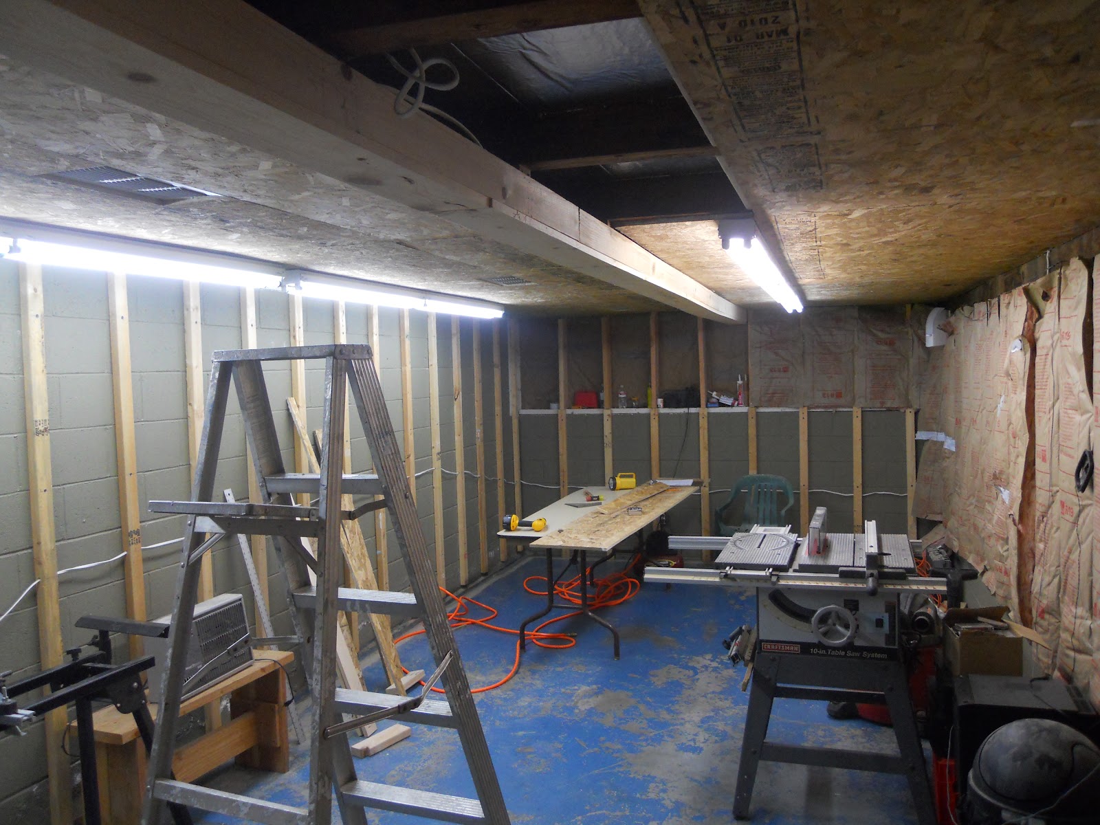
With the outside complete I turned my attention to the interior. Photo below shows insulation in place on the outside wall and furing strips being place on the far wall. At this point I was still using the original fluorescent's lighting.

I placed 2x3's to be used as furring strips against the west facing concrete wall. Once mounted, they became the support for dry wall.


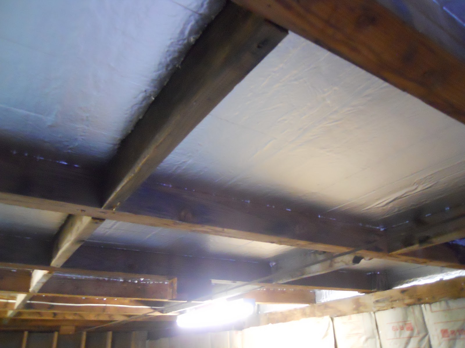
 Once this was done I turned my attention to the ceiling. I knew I was taking a risk here. Remember that the ceiling to the Placerville Branch is simply the underside of my porch. On the other hand I had never seen a water problem - even so much as a drop of water come through topside.  I insulated the ceiling with 1" insulating panels, cut to fit the roof supports.


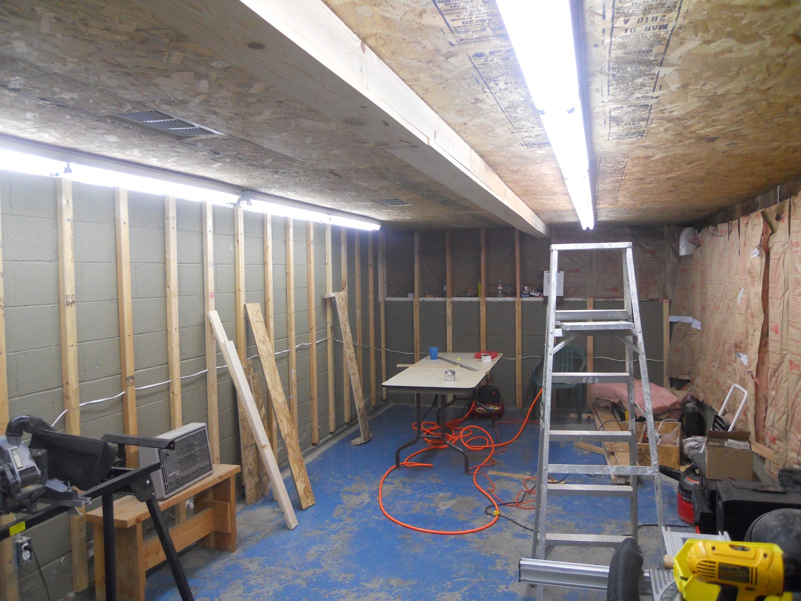
 The photo below shows the start of a series of 2 rows of working lights being installed, a box (upper middle) built around a cable that keeps the porch in tension. Hey I didn't build it! But someone must have thought that it was a good idea in 67. I built the box to hide the 1/4' steel cable and assorted hardware and it turned out to be a good place to hide my overhead lighting wiring as well.


 From this you can see the ceiling is complete and work is beginning on installing the lighting strips. I decided on T8 lighting which is bright enough to work under and provided adequate layout lighting later on. The lights are 6' double T8's with Philips daylight bulbs. You can read a ton of stuff about layout lighting on the web. Everyone has done lots of research on this subject. I wanted to have a bright light for my aging eyes is all. My choice gives me that. Later I moved both series of lights closer to their respective walls and centered them over the layout. Lastly I've started my wiring for outlets around the room. I'll write more about that in my next segment.


 I'll have one more round of room construction photos, then this section will be complete.
Stay tuned.


Sunday, March 2, 2014

Beginnings - 2 More Room construction photos

After the joists were in place, we wanted to get up the exterior wall portion. We used typical T11 siding as is used throughout the rest of the home. 
Exterior eastward facing wall

Interior view of newly built tyvek wrapped wall


Note door flows inward as most do. This had to be corrected later on since a duckunder was in order. From this photo you can see the underside of the porch, a couple of florescent lights giving me minimal light in the space. Nonetheless the space is now defined. 27' long by 11' wide. A narrow rectangle for sure.
       
Entrance to my wine cellar, furnace room, house foundation,
soon to be modeling room and one day Dispatchers Office!


This entrance above had to remain for access so I lost several feet on this side of the layout room to make the zig-zag. I suppose when my furnace goes we'll have to take it out in pieces!

Painted and ready to go


Yet more room construction photos next time.

Wednesday, January 29, 2014

Beginnings

The earliest photo's of my HO scale inspired Placerville branch are shared here. Originally slatted as a garage build and even getting as far as installing insulation in the portion I thought I would take over, was suddenly changed when my wife bought a new car and I foresaw nothing but an endless series of mishaps between building my railroad adjacent to a newly acquired auto. My second choice, suggested by my wife actually, was to build out a room underneath the back porch. I know it sounds crazy and my friend Phil Gulley who helped me along the way thought so too.

The under porch area with 2x6 studs going up
The area had been used as a open storage and work room. We started with studs on the open face.

Front entrance opening

The door behind leads to a small wine cellar, which eventually will share the space with my modeling room.


View from inside (as it were) facing north


The photo above shows the interior. To the left a full concrete brick wall, a partial wall is in front, with the open face towards my backyard to the right. Note the ceiling is 2 and 4 by's in a square pattern. Above that is plywood and above that is a vinyl or metal covering which is surprisingly keeps water out. This was something I worried about constantly. But in the 4 years that I've been building water leakage from above has never been a problem.

Opposite view looking south toward entrance

More construction photos next time.